
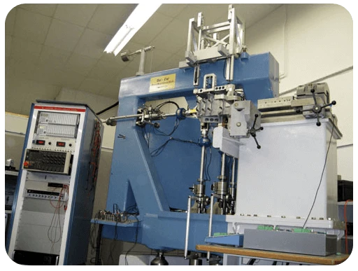
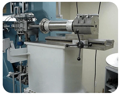
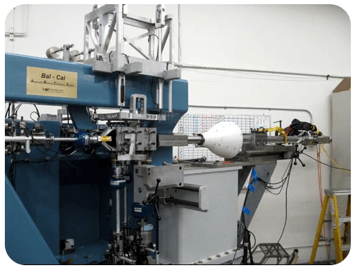
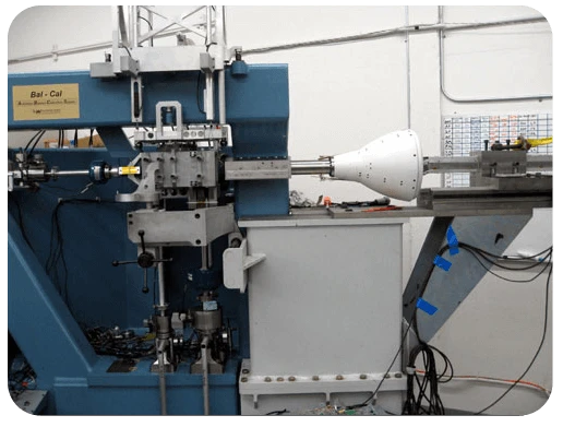
Balances may be calibrated either via a manual calibration process or by using the Automatic Balance Calibration System (ABCS); this is the only machine of its type located in the United States. The unique ABCS uses load cells, hydraulic actuators, and a computer control and data acquisition / reduction program to automatically generate an extensive balance calibration in very short time. It is capable of simultaneously loading all six balance components to obtain a third-order, 6 X 96 balance calibration matrix that is more representative of actual in-test load conditions than a calibration produced by manual loading. In addition, calibrations can be tailored for expected test loads.
The Automatic Balance Calibration System (ABCS) is capable of fully characterizing the coefficients of a six component internal strain gage balance in just a few hours. The advantage to automated loadings of the balance is the ability to fully calibrate the balance without the need to reposition the balance and the ability to reduce bias from the calibration process. The unique ability of the ABCS to apply any combination of loads allows it to apply any calibration load schedule, which includes six component wind tunnel test load combinations to validate the performance of the balance in actual test type conditions.
Some of the benefits of this system include:
- Full Six Component combined loadings
- Calibrations represent true test conditions
- Affordable, high accuracy calibrations in less time
- Conforms to AIAA Recommended National Balance Calibration Standards Formats
- Fully Automated
- 2~3 days vs. 4-6 weeks for manual calibration
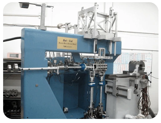
The load cells are changed to match the load range of the balance, by matching the load range for each balance the machine is able to provide increased resolution and accuracy for a wide range of balances. A second load adapter accommodates smaller balances with lighter loads. We have been able to characterize balances from .65 inches in diameter with very low loads to balances up to 8 inches in diameter that require the full capacity of the ABCS.
Standard ABCS Calibration Process
The standard method of calibrating most of our internal balances is to use the Automatic Balance Calibration System (ABCS) with several individual calibrations being performed during the calibration process. The standard ABCS load schedule (935 to 1970 points) is performed, loading every component with incremental cycles of a single component and in combination with every other component at incremental steps. The full load schedule completes all four quadrants of each component plotted vs. the other 5 components. A repeat of the load schedule is completed to document repeatability and to have a separate set of data to cross calculate and check the matrix. A generic six component load schedule developed to simulate a typical wind tunnel pitch sweep is applied to the balance during the ABCS cal process. This verifies balance performance in actual multi-axis test type load conditions. The balance is also loaded with manual dead weight loads to verify the performance of the calibration versus dead weight loadings. The standard calibration procedures have been developed since we began ABCS calibrations in 1997 and continue to mature and change as new requirements are requested.
ABCS Load Ranges
| Component | Max. Allowable | Max. Used |
| Normal Force (lb) | 11,000 | 11,000 |
| Pitch Moment (in-lb) | 80,000 | 25,000 |
| Side Force (lb) | 5,000 | 5,000 |
| Yaw Moment (in-lb) | 16,000 | 16,000 |
| Roll Moment (in-lb) | 18,000 | 18,000 |
| Axial Force (lb) | 2,500 | 2,200 |
Representative Calibration Results
| Component | N1 | N2 | Y1 | Y2 | R1 | X1 |
| Accuracy at high roll load | .02% | .03% | .04% | .06% | .14%* | .03% |
| Accuracy at mid roll load | .02% | .03% | .03% | .05% | .05% | .03% |
| Accuracy at low roll load | .02% | .03% | .02% | .03% | .03% | .02% |
Standard Deviations % of Balance Maximum Design Load
Stretching the Limits
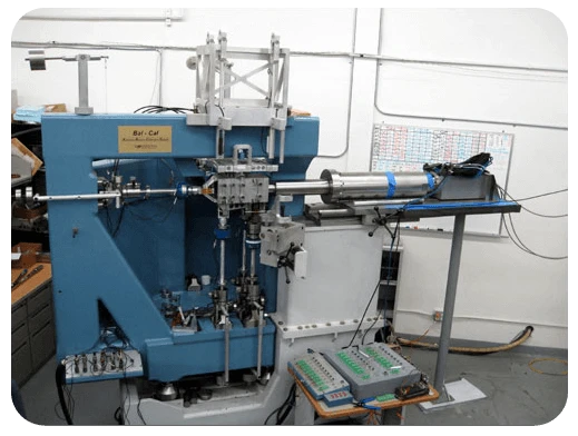 The ability to define the applied loads at the BMC inside of the load adapter allows the balance to be characterized with the Reference moment center redefined at almost any location. We have calibrated other balances well outside of the ABCS cal adapter. The recent calibration of a roughly 2 meter long air balance required a modification of the balance mounting attachment to the ABCS machine. We added a 4 foot diving board with a support column that is movable. This balance attached to a vertical back stop that attached to the top of the diving board. The diving board attaches to the repositioned non-metric attachment plate of the ABCS. This extended attaching method allows the balance assembly to be calibrated with the standard ABCS calibration procedure. The ABCS is able to apply a pure single component load at any location by using a positive load on the NF actuator and a negative load on the PM actuator. A pure NF or PM may be applied to the balance even with the balance located well aft of the machine’s reference center. The 2 meter long air balance was calibrated using a moment reference center that was 43 inches forward of the balance moment center and 10 inches aft of the ABCS moment reference center. This location is where the model attachment location will be for the wind tunnel test hardware.
The ABCS data system has 25 balance channels available. This allows back up bridges to be calibrated at the same time as the primary bridges so that a repeat loading is not required.
 |
 |
 |
 |